CO2monitorWifi
CO2 monitor assembly instructions
The goal of this project was to have a low-cost but accurate CO2 monitor, so that we could make a bunch of them to hand out to university workers to assess the air quality in their work spaces, including classrooms.
Overview
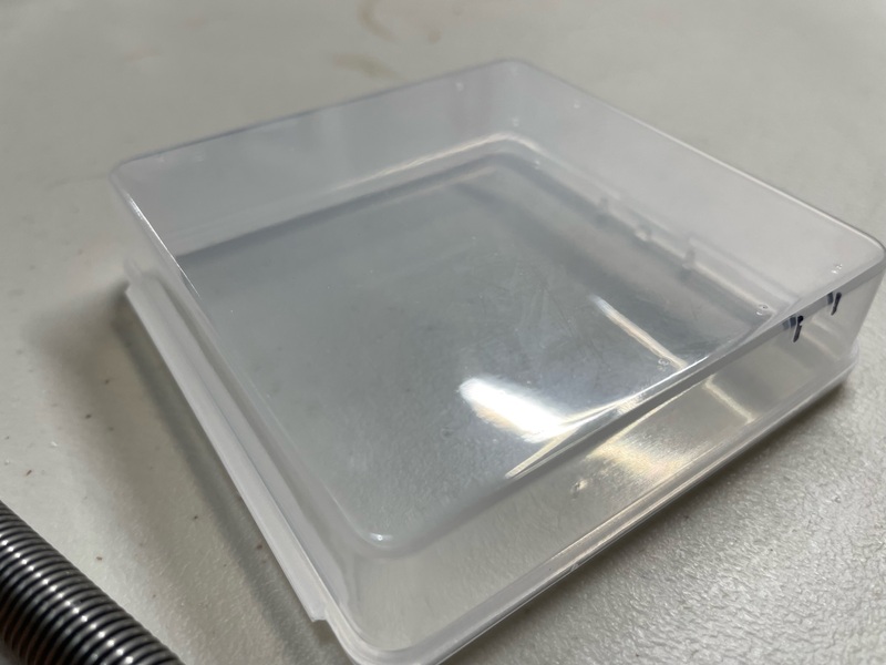
We got a pile of small clear plastic boxes, 3.2” square and a bit less than 1” tall. It just barely fits the LCD display we’re using.
We mount the LCD display and the ESP32 microcontroller inside the box, with the LCD display facing down and out. We need to drill holes in the box for screws to mount these components, plus a cut-out for the sensor (so that it can get outside air) and a cut-out for a micro-USB cable give power to the microcontroller.
There is a bit of soldering to do. We solder two pairs of header pins onto the sensor, and then we solder some wires together so that both the sensor and the LCD display can be plugged into the VIN pin on the microcontroller. The drilling and cutting and soldering are the hard parts of this assembly. We then connect the components with pre-made female-to-female jumper cables.
Prepare the box
There’s a drill template document that you should print out, to guide the positioning of the drill holes and cut-outs.
When printing the drilling template, make sure the sizes are kept the same (in particular, don’t let it “shrink to printable area”).
Tape the template to the bottom of the box, making sure the lid opening is oriented correctly. Most important is lining up the top and sides, because the LCD display is a very tight fit. (The LCD display we’re using has screw holes separated by 75mm left/right and 31mm top/bottom. If yours is different, you’ll need to adjust the R code for the template].
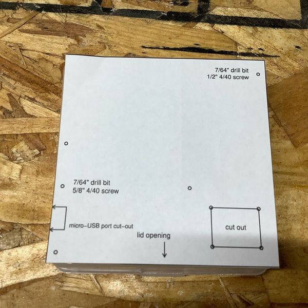
It seems easiest to use a 1/16” drill bit at each of the 9 spots (the two holes for the LCD display, the three holes for the microcontroller, and the four corners for the cut-out for the sensor). We then go back and use a 7/16” drill bit to enlarge the holes for the LCD display and the microcontroller. (The very small holes at the corners of the cut-out are sufficient to get started cutting with a small exacto blade.)
Before removing the template, mark the cut-out for the micro-USB with a sharpie.
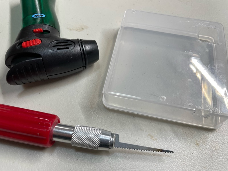
When cutting in plastic, it can be useful to heat the blade with a lighter or small torch.
For the cut-out for the sensor, I use a very thin exacto saw (see the photo below). I drill 1/16” holes in the corners to help get started with cutting the rectangle.
For the cut-out for the micro-USB, I don’t use starting holes. I just heat the blade and let it melt down through the plastic and then start cutting.
I should have said: don’t forget to wear eye protection (for me, reading glasses).
Solder headers onto the components
I’m using two pairs of breakaway male header pins for the S8 sensor. It’s tricky to hold them in place for soldering. And you don’t want to mess up a US$ 40 sensor.
Page 3 of the SenseAir S8 specs shows the pin assignments.
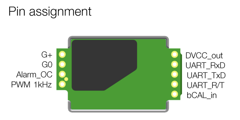
We want two pins on the 4-pin side, which nicely has labels: G+ on the end, on G0 next to it. Then we want two pins on the 5-pin side, one in the middle (TX) and the one to its right (RX), in the same direction as the ones we’re doing on the 4-pin side.
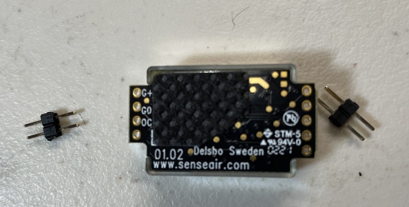
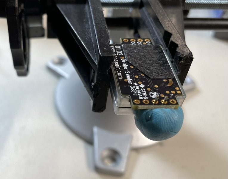
The easiest way to hold the pins in place for soldering is probably “blu tack”: that blue putty for hanging posters.
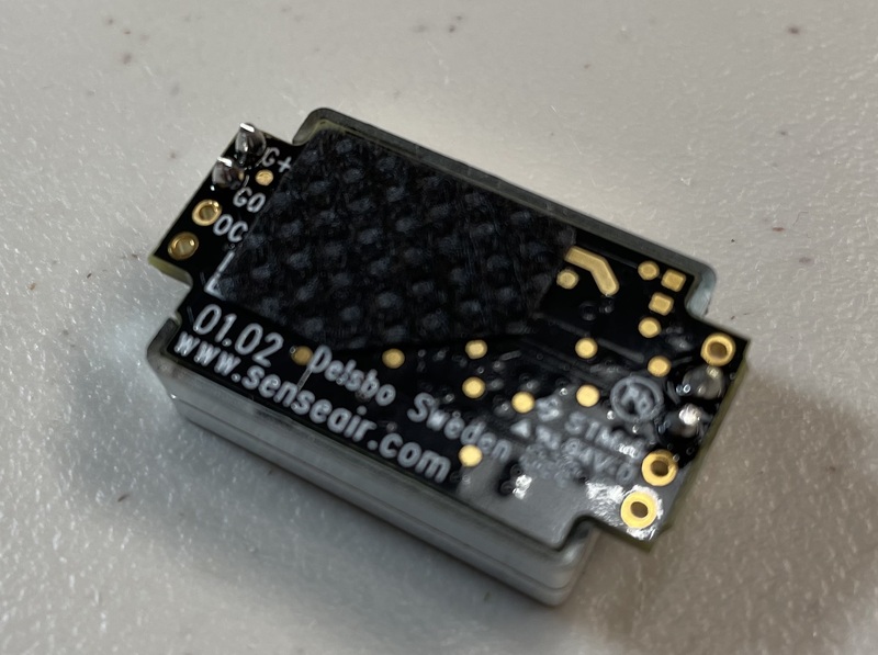
Here’s the final product. It’s not my best work, but the photo is blurry enough that you can’t tell.
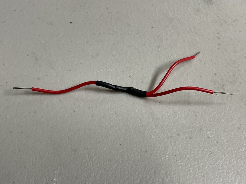
We also need to solder three 22-gauge wires together, so that we can connect both the LCD display and the sensor to the VIN pin on the microcontroller. I cover the soldered joint with a bit of heat-shrink tubing. (I used 3/32” tubing. You could maybe get by with 1/16” if your soldering isn’t as sloppy as mine.)
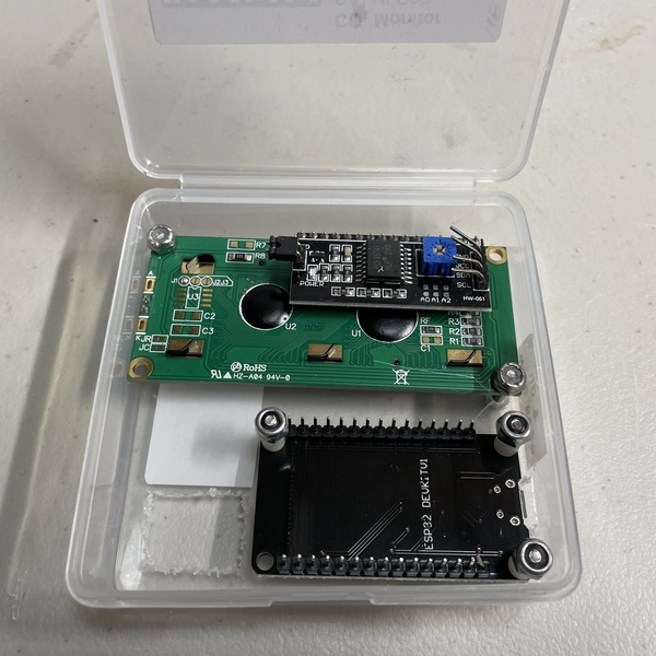
Mount the components
To mount the LCD display, I use two 1/2” 4/40 screws with round heads, with the heads outside the box, and two lock nuts.
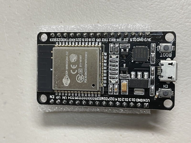
The particular ESP32 microcontroller is a 30-pin DOIT DevKit-v1 with a micro-USB connector and four big mounting holes.
To mount the ESP32 in the box, I use three 5/8” 4/40 screws with round heads, and again with the heads outside the box, plus three 1/4” plastic stand-offs, and three lock nuts. The stand-offs gets things above where the pins are, and also should help prevent any short-circuits from the metal screws.
I get these small screws and nuts McMaster-Carr.
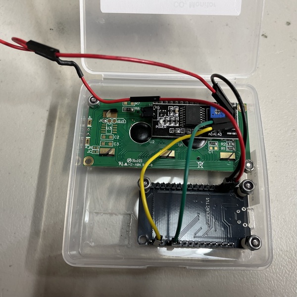
Make connections
To make the connections, I use 9 female-to-female jumpers, 2 each of three colors: green, yellow, and black, and then 3 red. They’re not very permanent and so they could eventually get rattled loose, but super easy and allow us to reconfigure things if necessary.
You’ll need to bend back the pins (carefully) on the LCD display, and bend them apart a bit, two above and two below the blue contrast potentiometer. Otherwise you won’t be able to close the lid.
The 16x2 LCD with I2C has a 4-pin connector:
-
16x2 GND → ESP32 GND (black)
-
16x2 VCC → red patch wire → ESP32 VIN (red)
-
16x2 SDA → ESP32 D21 (green)
-
16x2 SCL → ESP32 D22 (yellow)
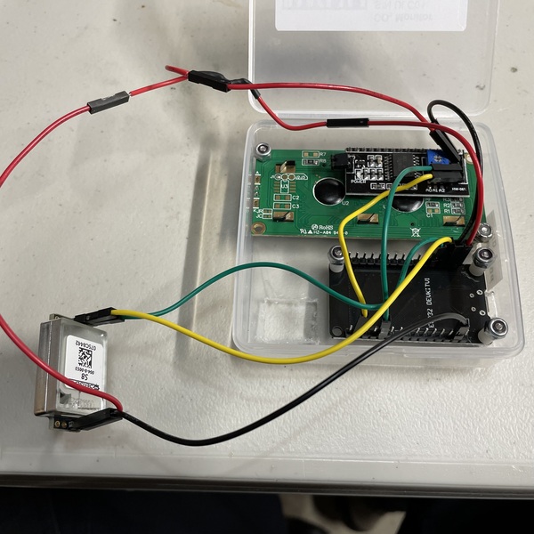
The SenseAir S8 connections are the following:
-
4-pin side, pin 1 (G+) → red patch wire → ESP32 VIN (red)
-
4-pin side, pin 2 (G0) → ESP32 GND (black)
-
5-pin side, pin 2 (UART RX) → ESP32 D12 (green)
-
5-pin side, pin 3 (UART TX) → ESP32 D13 (yellow)
Google form
The connection to wifi with the ESP32 is in order to dump the data to a google spreadsheet on the web. This is done through a google form. For more discussion of the process, see this blog post. You need to create a form and grab the form identifier plus the cryptic field identifiers that google creates.
-
Go to https://forms.google.com and start a new blank form.
-
Give it a name, create a first question (as the variable name you want in the column in the final spreadsheet), select Short answer in the drop-down menu, and then click the plus sign in the circle on the far right to create another field, or click the Send button on the top-right when you’re done.
-
At the end, grab the full link to the form, which includes (after
forms/d/e) the super-long form ID that you’ll need. -
Open the form in Firefox and click Ctrl-Shift-I to open the “Inspector”. Then poke through the html to find the
<form>element. If you poke around inside there, you’ll find the<input>elements. You’re looking for their names, as they have the field names that google uses, and which you will use when you want to post data programmatically. They’ll look something like this:<input type="hidden" name="entry.1240506587" value=""> <input type="hidden" name="entry.1745392992" value="">Those
entry.###names are used in the API call to push data to the google spreadsheet. -
Go to your form at https://forms.google.com and you’ll find three tabs: Questions, Responses, and Settings. If you click Responses, there’s a little green box with a white cross in it; click that to create a spreadsheet to collect your results.
Load the software
Download and install the Arduino IDE.
Open the IDE, and then use a micro-USB cable to connect your ESP32 to your computer.
The first time you use one of the ESP32 microcontrollers, it’s a bit of work to set things up:
-
In the Arduino IDE, Click File → Preferences
-
In the Additional Boards Manager URLs field, add:
https://raw.githubusercontent.com/espressif/arduino-esp32/gh-pages/package_esp32_dev_index.json -
Then go to Tools → Board → Boards Manager
-
Search for “ESP32” and click Install on “ESP32 by Espressif Systems”
-
Finally you can select your board: click Tools → Board → ESP32 Arduino and then ESP32-WROOM-DA. (There is a DOIT ESP32 DEVKIT V1 option, but strangely the built-in LED flickers to indicate that wifi is connected when I use ESP-WROOM-DA but not when I use DOIT ESP32 DEVKIT V1.)
You’ll also need to install some libraries. Click Tools → Manage Libraries. Then search for and install these libraries:
Finally, under Port (farther down in the Tools menu), you need to select the USB port for your board. Hopefully you’ll see just one choice. If you have trouble, try using a different micro-USB cable.
Download the software for this project,
CO2monitorWifi.ino
and open it in the Arduino IDE. Upload it to your board, and it’ll
immediately start running.
Note that you’ll need to create the required private.h file that
defines the wifi SSID and password, a google form identifier, and the
cryptic field names for the google form. The file not_private.h (which is not used) provides
examples: If HOME is defined (for
example, with #define HOME true), standard wifi WPA2 is used and we
need PRIVATE_SSID and PRIVATE_PASSWORD. Otherwise, enterprise WPA2
is used (for me, eduroam at my university) and
EAP_USERNAME and EAP_PASSWORD are needed. For the google form, we
need PRIVATE_API_CALL and five field identifiers like
PRIVATE_ENTRY1.
Adjust the LCD contrast
You will need to adjust the contrast on the LCD display, using a small screw to turn the blue potentiometer on the back of the LCD, near the wire connections. You probably won’t be able to read the text on the display until you do. It may work to just turn it all the way to the right (clockwise).
Tape the box shut
If it’s working, you can arrange the sensor as you want it and then delicately close the lid so the wires all stay inside and so they push the sensor down against its opening.
Tape the box shut with a couple of pieces of clear tape.
Power the project
You use the same micro-USB port to power the project as to load the software. You should be able to use any USB power adapter. You should also be able to use any USB backup battery, like for a phone. Or you can power the project with a USB port in a computer.
Calibration
These SenseAir S8 including some auto-calibration feature (automatic baseline calibration, ABC). It considers past measurements and makes an adjustment up or down, changing the baseline by no more than about 30-50 ppm every 8 days.
If you place the CO2 monitor outside in fresh air for 5-10 minutes, it should give a reading that is close to 420 ppm. If it reads much too high or much too low (say 320 or 500), you may want to manually calibrate it.
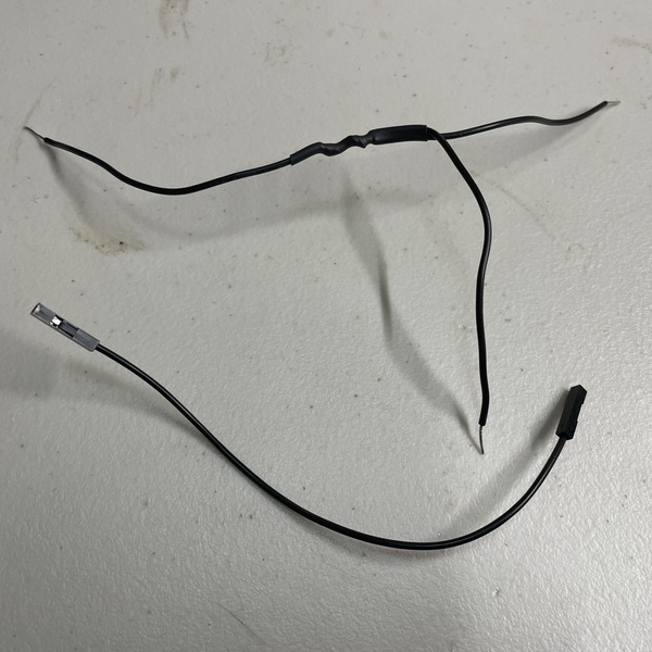
I did this by soldering three 22-gauge solid wires together and then using that plus a female-to-female jumper.
Turn the unit off. Remove the black wire from the SenseAir S8 sensor and plug the three-way wire there and into ground on the ESP32. Turn the unit back on; it should be working normally. And you have one open connection on your three-way wire. You then when to touch that to the 5th pin on the 5-pin side of the SenseAir S8 (two holes away from your yellow wire, on the other side from the green wire) for more than 4 seconds but less than 8 seconds, so go for 5 seconds. It should then reset the baseline to 400 ppm. (If you connect the pin to ground for more than 8 seconds, it will reset the baseline to 0 ppm, which you definitely don’t want.)
So, following the instructions from Mariete:
-
Leave the monitor running, out in fresh air, for 15 minutes
-
Touch that bCal_in pin to ground for 5 seconds
-
Let it continue running for another 5 minutes
That’s the theory, anyway.