CO2monitor
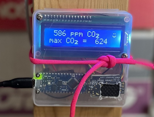
CO2 monitor based on an Arduino and a SenseAir S8 sensor
This is a low-cost, do-it-yourself CO2 monitor based on the SenseAir S8 sensor, an Arduino Nano Every, and a 16x2 LCD display.
The goal is assess air quality, particularly in classrooms and meeting rooms and with concern about COVID-19. The main source of my understanding was LibreCO2. Also see this useful post by Mariete.
I did a limited comparison between two of these SenseAir S8-based monitors and the more expensive Aranet4; see the results.
Parts
The cost of the main components is about US$ 60. (Most of the cost is the sensor, which is about US$ 40. If you’re willing to wait a month for shipping, you can get it much cheaper via AliExpress).
To connect the components, you will need 8 female-to-female jumper wires, solder, a soldering iron, 2 2-pin male headers for the SenseAir S8 sensor, and maybe also 2 16-pin male headers for the Arduino (if you got one without headers installed).
To attach components to the box, you’ll need some small screws (I used 1/2” 4/40 screws for the LCD display), as well as some very small screws (I used 11/32” 0/80 screws for the Arduino). I get them from McMaster-Carr.
Code
You’ll find the code on Github.
The first time using the Arduino Nano Every with the Arduino
IDE, you may need to use the Board Manager to install the drivers
for the megaAVR boards. Then when you select the Nano Every as your
board, select Registers emulation: None (ATMEGA4809).
My code for interacting with the SenseAir S8 sensor is based on the example code in the S8_UART library.
My code for writing on the LCD (including making custom characters) was based on the example code with the older LiquidCrystal_I2C library (which is not compatible with the Arduino Nano Every).
Libraries
The code uses the following libraries to interact with the S8 sensor and the LCD display, respectively.
In the Arduino IDE, install these libraries with the Library Manager.
Assembly instructions
See the instructions document, which attempts to explain the full process:
-
Prepare the box (drilling holes to mount components and cutting holes for the sensor and the micro-USB cable)
-
Solder headers onto the main components
-
Mount the components in the box
-
Make connections (see below)
-
Load the software
-
Adjust the contrast on the LCD display
Connections
The 16x2 LCD with I2C has a 4-pin connector:
-
16x2 GND → Arduino GND (black)
-
16x2 VCC → Arduino VIN (red)
-
16x2 SDA → Arduino A4 (green)
-
16x2 SCL → Arduino A5 (yellow)
The SenseAir S8 needs soldering; you could use two pairs of header pins. See page 3 of the specs for pin information, which is not printed on the sensor.
-
4-pin side, pin 1 (G+) → Arduino 5V (red)
-
4-pin side, pin 2 (G0) → Arduino GND (black)
-
5-pin side, pin 2 (UART RX) → Arduino D10 (green)
-
5-pin side, pin 3 (UART TX) → Arduino D11 (yellow)
License
This work released under the MIT License.

