CO2monitor
CO2 monitor assembly instructions
The goal of this project was to have a low-cost but accurate CO2 monitor, so that we could make a bunch of them to hand out to university workers to assess the air quality in their work spaces, including classrooms.
Overview
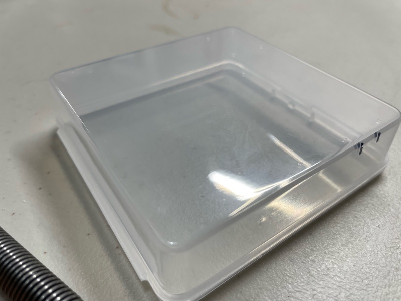
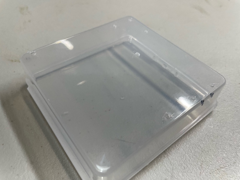
We got a pile of small clear plastic boxes, 3.2” square and a bit less than 1” tall. It just barely fits the LCD display we’re using.
We mount the LCD display and the Arduino inside the box, with the LCD display facing down and out. We need to drill holes in the box for screws to mount these components, plus a cut-out for the sensor (so that it can get outside air) and a cut-out for a micro- or mini-USB cable give power to the Arduino.
The Arduino may need header pins soldered on; the sensor definitely will. The drilling and cutting and soldering are the hard parts of this assembly. We then connect the components with pre-made female-to-female jumper cables.
Prepare the box
There’s a drill template document that you should print out, to guide the positioning of the drill holes and cut-outs.
When printing the drilling template, make sure the sizes are kept the same (in particular, don’t let it “shrink to printable area”).
Tape the template to the bottom of the box, making sure the lid opening is oriented correctly. most important is lining up the top and sides, because the LCD display is a very tight fit. (The LCD display we’re using has screw holes separated by 75mm left/right and 31mm top/bottom. If yours is different, you’ll need to adjust the R code for the template].
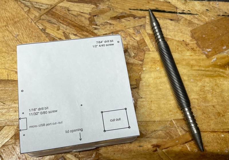
After breaking a bunch of boxes with a bunch tool (pictured above), I ended up finding that the easiest thing to do is just to drill directly through the template into the box with a 1/16” drill bit at each of the 9 spots. This small drill bit is pretty easy to line up and get started without slipping.
Before removing the template, mark the cut-out for the micro-USB with a sharpie.
Again, use the 1/16” drill bit for all nine positions. Then go back to the top two positions (top-right and middle-left on the template), which will hold the LCD display, and enlarge the holes using a 7/64” drill bit. These will take 1/2” 4/40 screws.
The other seven holes include three for the Arduino (in which I use 11/32” 0/80 screws) and four holes for the corners of the sensor cut-out.
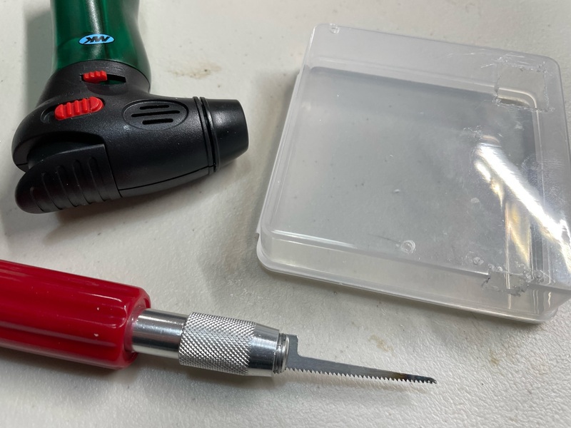
When cutting in plastic, it can be useful to heat the blade with a lighter or small torch. (I didn’t heat the drill bit for the drilling; doing so made it harder to find my starting dents and the bit tended to just melt right through, no drilling required, but generally not in the right location.)
For the cut-out for the sensor, I drill 1/16” holes in the corners to help get started with cutting the rectangle. I use a very thin exacto saw (see the photo below).
For the cut-out for the micro-USB, I don’t use starting holes. I just heat the blade and let it melt down through the plastic and then start cutting.
I should have said: don’t forget to wear eye protection (for me, reading glasses).
Solder headers onto the components
I’m using two pairs of breakaway male header pins for the S8 sensor. It’s tricky to hold them in place for soldering. And you don’t want to mess up a US$ 40 sensor.
Page 3 of the SenseAir S8 specs shows the pin assignments.
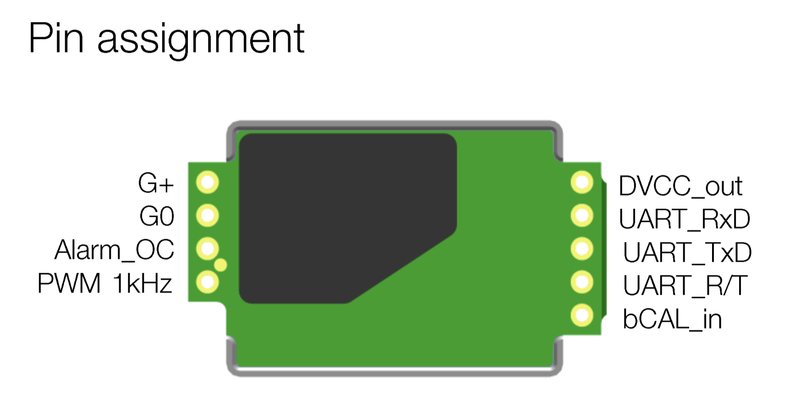
We want two pins on the 4-pin side, which nicely has labels: G+ on the end, on G0 next to it. Then we want two pins on the 5-pin side, one in the middle (TX) and the one to its right (RX), in the same direction as the ones we’re doing on the 4-pin side.
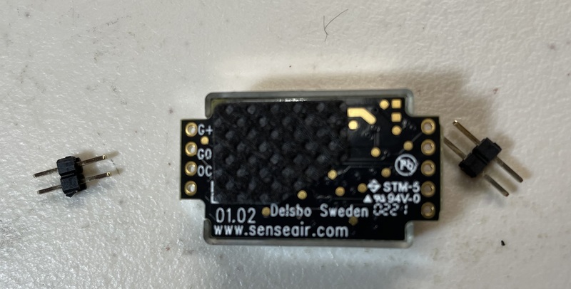
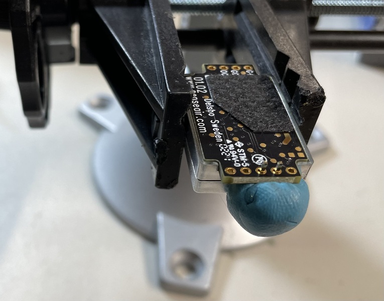
The easiest way to hold the pins in place for soldering is probably “blu tack”: that blue putty for hanging posters.
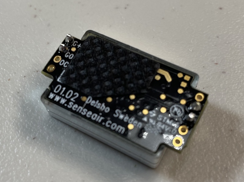
Here’s the final product. It’s not my best work, but the photo is blurry enough that you can’t tell.
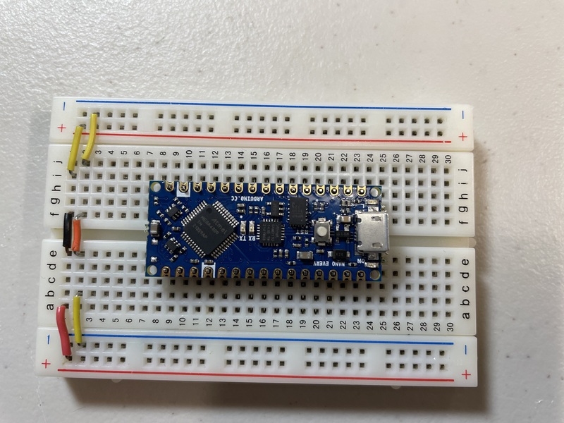
You can get an Arduino Nano Every with header pins already in place, but it’s a bit cheaper (and maybe more flexible) to get them without the header pins installed. While you might just solder the pins that are being used, it requires less thought and not much more time to just solder all the pins. The easiest way to hold the pins in place for soldering is to put it on a breadboard.
Mount the components
To mount the LCD display, I use two 1/2” 4/40 screws with round heads, with the heads outside the box, and two lock nuts.
To mount the Arduino, I use three 11/32” 0/80 screws, with the heads inside the box, and three hex nuts. (I would do it the other way-round, but I just couldn’t handle the tiny screws in the tight spaces to do it that way. I practically need tweezers to handle these screws.) You can cut off the excess screw with just an angle wire cutter, but don’t do it too short as you might want to take them off and put them on again and their length was the one thing they had going for them.
I get these small screws and nuts McMaster-Carr.
As mentioned below, we seemed to have trouble with shorts between the screws used to mount the Arduino and the micro-USB port. Maybe putting electrical tape on the corners of the board would help with this problem?
Make connections
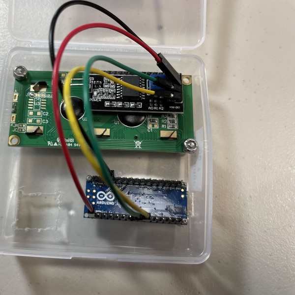
To make the connections, I use 8 female-to-female jumpers, 2 each of four colors: green, yellow, black, and red. Not very permanent and so they could eventually get rattled loose, but super easy.
You’ll need to bend back the pins (carefully) on the LCD display, and bend them apart a bit, two above and two below the blue contrast potentiometer. Otherwise you won’t be able to close the lid.
The 16x2 LCD with I2C has a 4-pin connector:
-
16x2 GND → Arduino GND (black)
-
16x2 VCC → Arduino VIN (red)
-
16x2 SDA → Arduino A4 (green)
-
16x2 SCL → Arduino A5 (yellow)
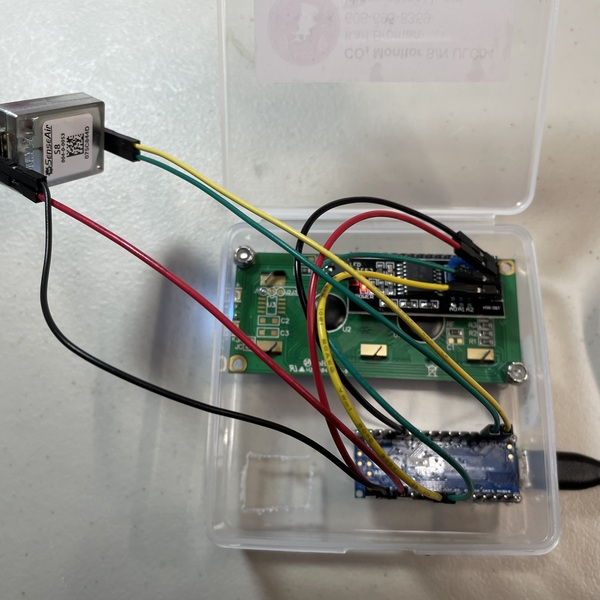
The SenseAir S8 connections are the following:
-
4-pin side, pin 1 (G+) → Arduino 5V (red)
-
4-pin side, pin 2 (G0) → Arduino GND (black)
-
5-pin side, pin 2 (UART RX) → Arduino D10 (green)
-
5-pin side, pin 3 (UART TX) → Arduino D11 (yellow)
Load the software
Download and install the Arduino IDE.
Open the IDE, and then use a micro-USB cable to connect your Arduino Nano Every to your computer.
Then select your board: On the menu bar, click Tools, and then select your board under Boards. If you don’t see it listed, click “Board Manager” at the top of the list and install the megaAVR boards. You may then have a choice between megaAVR and something else, and when you go into megaAVR, you’ll see the Nano Every as one of the options.
In that Tools menu, your board should show up as you having selected
Nano Every. Underneath that, select Registers emulation: None
(ATMEGA4809).
In the next item down in the Tools menu, you need to select your port. Hopefully you’ll see just one choice.
Download the software for this project,
CO2monitor.ino
and open it in the Arduino IDE. Upload it to your board, and it’ll
immediately start running.
While in some cases we were able to upload the software immediately, in other cases we got repeated error messages and couldn’t get the software to upload to the Arduino board. It seems that this was due to a short between the USB port and one of the screws used to mount the Arduino. Removing the screws, we were able to upload the software. In a couple of cases, there were run-time problems that seemed to be due to shorts with the mounting screws. In two cases, we removed the screw near pin D12, and in one case, we removed the screw near D13.
Adjust the LCD contrast
You will need to adjust the contrast on the LCD display, using a small screw to turn the blue potentiometer on the back of the LCD, near the wire connections. You probably won’t be able to read the text on the display until you do. It may work to just turn it all the way to the right (clockwise).
Tape the box shut
If it’s working, you can arrange the sensor as you want it and then delicately close the lid so the wires all stay inside and so they push the sensor down against its opening.
Tape the box shut with a couple of pieces of clear tape.
Power the project
You use the same micro-USB port to power the project as to load the software. You should be able to use any USB power adapter. You should also be able to use any USB backup battery, like for a phone. Or you can power the project with a USB port in a computer.
Calibration
These SenseAir S8 including some auto-calibration feature (automatic baseline calibration, ABC). It considers past measurements and makes an adjustment up or down, changing the baseline by no more than about 30-50 ppm every 8 days.
If you place the CO2 monitor outside in fresh air for 5-10 minutes, it should give a reading that is close to 420 ppm. If it reads much too high or much too low (say 320 or 500), you may want to manually calibrate it.
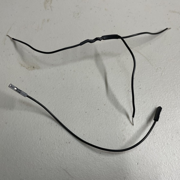
I did this by soldering three 20-gauge solid wires together and then using that plus a female-to-female jumper.
Turn the unit off. Remove the black wire from the SenseAir S8 sensor and plug the three-way wire there and into ground on the Arduino. Turn the unit back on; it should be working normally. And you have one open connection on your three-way wire. You then when to touch that to the 5th pin on the 5-pin side of the SenseAir S8 (two holes away from your yellow wire, on the other side from the green wire) for more than 4 seconds but less than 8 seconds, so go for 5 seconds. It should then reset the baseline to 400 ppm. (If you connect the pin to ground for more than 8 seconds, it will reset the baseline to 0 ppm, which you definitely don’t want.)
So, following the instructions from Mariete:
-
Leave the monitor running, out in fresh air, for 15 minutes
-
Touch that bCal_in pin to ground for 5 seconds
-
Let it continue running for another 5 minutes
That’s the theory, anyway.